How to Choose a Relief Valve Block in 2026?
Choosing a Relief Valve Block in 2026 requires more than comparing pressure ratings and purchase prices. This compact component can protect pumps, actuators, manifolds, and operators from damaging overpressure. A poor choice may cause leakage, unstable pressure, excessive heat, or difficult maintenance.
Hydraulic author Brendan Casey offers a useful warning: “A hydraulic system is only as good as its weakest component.” That principle fits every Relief Valve Block selection. Buyers should examine maximum working pressure, flow capacity, cracking pressure, response time, temperature range, sealing materials, and port configuration. Compatibility matters too. Mineral oil, water-glycol fluids, and biodegradable fluids can require different seal materials.
Small details matter.
A block rated for 350 bar may still perform poorly if its relief setting drifts under heat. A compact manifold may save space, yet restrict flow through narrow internal passages. Stainless steel can improve corrosion resistance, but it may increase cost and complicate machining. These trade-offs deserve honest review.
This guide focuses on practical selection for hydraulic power units, mobile equipment, industrial machinery, and test systems. It also considers inspection access, replacement availability, noise, contamination control, and documentation quality. Manufacturer data should be checked against real operating conditions, not copied blindly from a catalog.
No selection method is perfect. A calculation can miss vibration, pressure spikes, or neglected maintenance. That is why experienced engineers combine datasheets, field history, and controlled testing before approval. The right Relief Valve Block should protect the system quietly, repeatedly, and predictably throughout its service life.
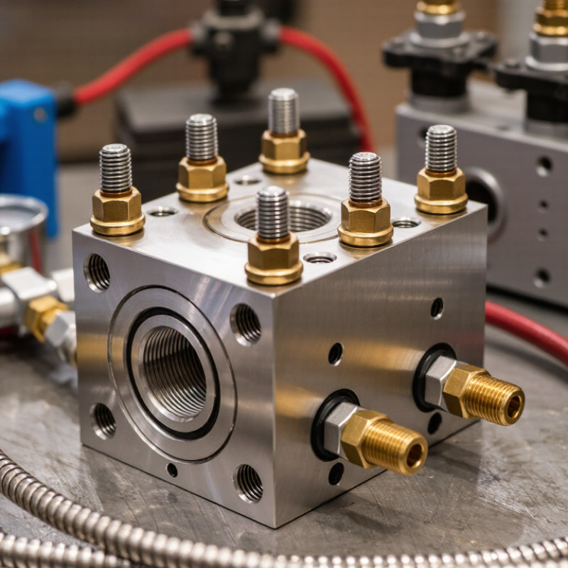
Define Relief Valve Block Types, Functions, and ISO 4413 Safety Requirements
Choosing a relief valve block in 2026 starts with pressure control, not price. Common types include direct-acting, pilot-operated, and modular manifold blocks. Direct-acting valves respond quickly and suit smaller flows. Pilot-operated designs handle higher flow with less pressure variation. A block may also include isolation valves, gauges, test ports, and unloading circuits. Its function is practical: limit excess pressure, release stored energy, and protect pumps, actuators, and operators.
ISO 4413:2010 requires hydraulic systems to prevent pressure from exceeding safe working limits. Relief settings should remain below the lowest rated component. Adjustment points should resist unintended changes, while trapped pressure needs a controlled discharge path.
The U.S. Bureau of Labor Statistics recorded 5,283 fatal work injuries in 2023, according to its Census of Fatal Occupational Injuries. That figure is not hydraulic-specific, but it reinforces a hard lesson: safety details cannot be treated as accessories. Incorrect sizing, blocked discharge lines, or hidden stored pressure can defeat a well-designed circuit.
Tips: Match the valve block’s rated flow, pressure, fluid compatibility, and temperature range to real operating conditions. Check pressure spikes, not only average pressure. Confirm every port marking on the schematic and the installed block. Ask whether maintenance staff can isolate and depressurize the circuit without reaching into danger. ISO 4413 compliance should be documented through calculations, inspection records, and functional testing. A selection based only on catalogue pressure may look efficient, yet it can be a weak decision when transient loads are ignored.
Match Rated Pressure, Flow Capacity, and Temperature to System Data
How to Choose a Relief Valve Block in 2026?
Match Rated Pressure, Flow Capacity, and Temperature to System Data
A relief valve block should match real system data, not a convenient catalog number. Check the maximum allowable working pressure, set pressure, and possible pressure spikes. Rated pressure must remain suitable at the operating temperature. For example, a block rated at 200 bar at room temperature may require derating at 120°C. Confirm this value in the technical documentation.
Flow capacity deserves equal attention. Use the required relieving rate, fluid density, viscosity, and allowable backpressure. Compare the calculated demand with the block’s certified flow coefficient. A small passage can create excessive pressure loss before the relief valve opens. Measure the inlet pipe length and count elbows. These details often change the result.
Temperature affects more than pressure rating. Inspect the body material, seal range, thermal expansion, and fluid compatibility. In field checks, I have found systems operating safely below their pressure limit but outside their seal temperature range. That mistake can remain hidden until maintenance. Record pressure and temperature near the connection point, not only from a distant control panel. I also recommend reviewing the calculation with a qualified engineer and checking the latest test documentation. A clean spreadsheet is useful, but it can still contain the wrong assumptions.
How to Choose a Relief Valve Block in 2026?
Match rated pressure, flow capacity, and temperature to the system’s maximum operating data. The reference values below use common hydraulic and process design ranges; final selection must be verified against the complete equipment datasheet, pressure spikes, fluid compatibility, and applicable standards.
Select a valve block with a rated pressure above the system maximum, a flow capacity at or above the required flow, and a temperature rating that covers the highest expected fluid temperature. The selected rating should also account for transient conditions and the manufacturer’s derating requirements.
Calculate Pressure Settings Using the 10% Overpressure Industry Criterion
How to Choose a Relief Valve Block in 2026?
Calculate Pressure Settings Using the 10% Overpressure Industry Criterion
Choosing a relief valve block starts with the protected equipment, not the valve body. Confirm the vessel’s maximum allowable working pressure, design temperature, fluid condition, and required flow capacity. A practical field check includes pipe size, discharge routing, corrosion exposure, and access for testing. Small details matter. A blocked outlet can defeat good calculations.
Under the 10% overpressure criterion, a valve should achieve its rated relieving capacity when pressure reaches 110% of the set pressure. For example, a vessel with a 10 bar allowable pressure may require a set pressure at or below 10 bar, while full capacity occurs near 11 bar. Do not simply add 10% to the set pressure without checking the governing pressure-equipment code. Set pressure, accumulation, blowdown, and operating pressure are different values. I have seen selection errors caused by treating them as identical.
Tips: Keep normal operating pressure comfortably below the set point, often by reviewing the manufacturer’s recommended margin. Verify the block arrangement prevents accidental isolation of a protected vessel. Use calibrated gauges and document every assumption. Recheck the calculation after changing fluid temperature or valve trim. Codes differ. Local review remains essential.
How to Choose a Relief Valve Block in 2026? - Calculate Pressure Settings Using the 10% Overpressure Industry Criterion
Calculation basis: Relieving Pressure = Set Pressure × 1.10. The selected set pressure should not exceed the protected equipment MAWP. Final sizing and certification must follow the applicable pressure-vessel and relief-device standards. | Service | Protected Equipment MAWP
(bar g) | Normal Operating Pressure
(bar g) | Recommended Set Pressure
(bar g) | 10% Overpressure
(bar) | Calculated Relieving Pressure
(bar g) | 110% of MAWP
(bar g) | Pressure Check |
| Saturated steam vessel | 10.0 | 8.0 | 9.5 | 0.95 | 10.45 | 11.00 | Pass |
| Compressed air receiver | 16.0 | 12.0 | 15.0 | 1.50 | 16.50 | 17.60 | Pass |
| Hot-water storage vessel | 6.0 | 4.5 | 5.5 | 0.55 | 6.05 | 6.60 | Pass |
| Process gas separator | 25.0 | 20.0 | 24.0 | 2.40 | 26.40 | 27.50 | Pass |
Relief Valve Block Selection Guide
| Selection Dimension | Recommended Design Choice | Typical Application | Key Verification Point |
| Block arrangement | Single relief-valve block with a full-flow inlet passage | Non-critical vessels with one relief device | Inlet pressure loss should remain within the applicable design limit |
| Maintenance isolation | Lockable isolation arrangement with clear open-position indication | Systems requiring periodic inspection or removal | The protected equipment must not be left without required overpressure protection |
| Fluid compatibility | Carbon steel for compatible dry services; stainless steel or alloy construction for corrosive or wet services | Air, steam, water, hydrocarbons, and corrosive process fluids | Check corrosion resistance, seal compatibility, and fluid cleanliness |
| Temperature range | Select body, trim, and gasket materials for the complete design temperature range | Steam and hot-process applications | Confirm pressure-temperature ratings at the maximum metal temperature |
| Connection size | Choose the inlet and outlet connection based on certified relief capacity and piping layout | Gas, vapor, steam, and liquid relief systems | Do not select size from line diameter alone; verify required relieving flow |
| Discharge routing | Use a supported discharge connection directed to a safe collection or vent system | Toxic, flammable, hot, or environmentally sensitive fluids | Consider back pressure, reaction forces, drainage, and personnel exposure |
| Documentation | Require set-pressure data, certified capacity, materials, test records, and inspection instructions | All pressure-relief installations | Confirm conformity with the governing code and local regulatory requirements |
Calculation example: For a set pressure of 15.0 bar g, the 10% overpressure is 15.0 × 0.10 = 1.5 bar, and the calculated relieving pressure is 15.0 × 1.10 = 16.5 bar g.
Compare 2026 Smart Monitoring, Certification, Maintenance, and Total Cost
How to Choose a Relief Valve Block in 2026?
In 2026, select a relief valve block by measuring control, compliance, and lifetime cost. Smart monitoring should record pressure, temperature, valve position, and test history. Deloitte’s 2024 Smart Manufacturing and Operations Survey found that 86% of manufacturing leaders view smart manufacturing as important for competitiveness. However, that figure is not valve-specific. A dashboard alone does not improve safety. Poor sensor calibration can create false confidence.
Certification remains a practical filter. Check compatibility with ASME BPVC, API 520, API 526, and ISO 4126 requirements. Local regulations may add inspection or documentation duties. Confirm material certificates, pressure ratings, temperature limits, and test procedures before purchase. The U.S. Department of Energy’s Operations & Maintenance Best Practices Guide reports that preventive maintenance can reduce costs by 12–18% compared with reactive maintenance. McKinsey maintenance research also indicates predictive programs may reduce downtime by 30–50%. Results vary widely. Data quality matters more than slogans.
Tips: Calculate total cost over five years. Include calibration, spare seals, technician hours, software fees, testing, and lost production. Choose a block with clear isolation status and accessible test points. Ask for digital records, not only paper certificates. One overlooked issue is human behavior. Operators may bypass alarms during nuisance alerts. A simpler system, properly tested, can outperform a sophisticated system nobody trusts. Review the choice after the first inspection cycle. Your original assumptions may be wrong.
