
How to Improve CNC Machining Precision?
A precision part can look flawless and still miss its drawing by a few microns. That gap often begins before the cutter touches metal. CNC machining precision depends on the machine, tool condition, material, workholding, and measurement method working together. A worn end mill may leave a faint taper. A warm spindle can shift a critical dimension during a long run. Small shifts matter.
Improvement starts with evidence, not guesswork. Record dimensions at setup and after the machine reaches a stable operating temperature. Check tool runout, inspect cutting edges, and confirm that the workpiece sits firmly against clean locating surfaces. Use a calibrated micrometer or suitable measuring instrument, and compare results with the part drawing and tolerance requirements. These steps help identify whether the problem comes from tooling, setup, cutting conditions, or inspection.
The process is rarely perfect on the first attempt. A change to feed rate may improve surface finish but affect cycle time or tool wear. That trade-off deserves a real test, not an assumption. Keep notes on each adjustment, including material batch and tool life. Then change one factor at a time where practical. No checklist fixes every setup; that is easy to forget when production pressure builds. A disciplined review of machine condition, cutting strategy, temperature, and measurement gives teams a clearer path toward repeatable results.
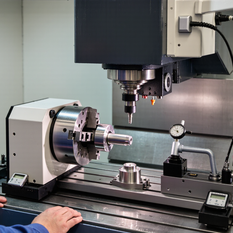
Define the Target: ISO 286 Specifies IT01–IT18 Tolerance Grades
ISO 286 defines IT01 through IT18 as standardized tolerance grades for linear dimensions. IT01 allows the narrowest tolerance; IT18 allows the widest. The actual tolerance width also depends on the nominal size, so an IT grade alone is not a complete limit. Check the relevant ISO 286 table for the dimension range before setting drawing values.
Choose a grade based on function, not on the assumption that tighter is always better. A sliding pin and bore may need a controlled fit, while a non-critical cover dimension may not. For example, specify the nominal size, tolerance grade, and any required upper or lower deviation clearly. Small details matter. Tighter limits can increase inspection time, scrap risk, and machining cost without improving how the assembly works.
ISO 286 addresses dimensional tolerances, not every source of precision error. It does not replace controls for form, surface texture, or measurement conditions. A part near its limit can read differently if it is warm or measured with unsuitable equipment. Use calibrated gauges suited to the feature, and verify the process across multiple parts. A neat tolerance table can still hide a poor choice. Review the fit in the actual assembly, and revise the grade if the function does not justify its demands.
Set the Reference Temperature: ISO 1 Uses 20 °C for Dimensional Measurements
CNC precision depends on more than tool paths and cutting conditions. Temperature matters too. ISO 1 sets 20 °C as the reference temperature for dimensional measurements. A part measured at another temperature may not match its reported size at that reference, because materials expand or contract as they warm or cool.
Consider a 100 mm steel component. Near room temperature, a 1 °C change can alter its length by roughly 1 micrometre, though the exact value depends on the alloy. Small differences matter. A part measured straight after machining may still be warm, while a cool inspection room can change its dimensions again. Real shops are not perfect laboratories, and holding every area at exactly 20 °C can be difficult.
Let parts, gauges, and fixtures settle near the inspection-room temperature before checking tight tolerances. Record the temperature when results are close to a limit. If measurement happens away from 20 °C, account for the material’s thermal expansion where appropriate; do not assume every alloy behaves like steel. Keep hands off precision surfaces when possible, since even brief contact can add heat. It is easy to overlook this step. A simple temperature log beside the inspection record can reveal whether a recurring size shift comes from machining or measurement conditions.
How to Improve CNC Machining Precision? Set the Reference Temperature
ISO 1 specifies 20 °C as the standard reference temperature for dimensional measurements.
The chart shows estimated dimensional change for a freely expanding 100 mm part, relative to 20 °C. It uses approximate linear expansion coefficients of 11.5 µm/(m·°C) for steel and 23.1 µm/(m·°C) for aluminum. Actual values vary by alloy and conditions, so temperature control and measurement at a consistent reference temperature help reduce dimensional error.
Manage Thermal Drift: Steel Expands About 11.5 µm/m per °C
How to Improve CNC Machining Precision?
Steel expands by about 11.5 µm per meter for every 1°C rise. A one-meter steel bar warming by 10°C can grow roughly 115 µm. That shift may exceed a tight machining tolerance. The exact value varies with alloy and temperature, so treat it as a useful estimate, not a guaranteed measurement. Small shifts matter.
Thermal drift affects more than the workpiece. Machine structure, spindle, tooling, and even a probing fixture can warm at different rates. Run the machine through a consistent warm-up cycle before precision work, then allow the part and measuring equipment to reach a stable temperature. Keep hot chips away from finished surfaces, and avoid placing stock in direct sunlight. Coolant temperature matters too; a sudden change can alter both the workpiece and machine behavior. Perfect temperature control is rarely practical, and it is easy to overlook a small source of heat.
Tips: Record shop and part temperatures during inspection. If a part is measured cold but machined warm, account for the difference. Recheck critical dimensions after temperatures stabilize, using the same measurement method each time. I would not trust a single reading when a few microns decide acceptance; repeat it, and question unexpected results.
Verify Axis Performance: ISO 230-2 Tests Positioning Accuracy and Repeatability
A CNC axis can appear to move smoothly and still miss its commanded position. ISO 230-2 provides a repeatable method for measuring positioning accuracy and repeatability along an axis. Small errors matter. They can show up as mismatched hole locations or uneven spacing across a machined part.
A typical test uses a calibrated measuring system, such as a laser interferometer, while the axis moves through defined positions. Measurements are taken in both travel directions, because backlash and other direction-dependent effects can change the results. At each position, repeated readings help reveal how consistently the axis returns. The test report can show positioning deviations, repeatability, and measurement uncertainty. These figures help separate a consistent offset from less predictable variation.
Control the setup. Stabilize the machine and measuring equipment, check the test environment, and document the test conditions. Otherwise, heat or vibration may distort the readings. Use the results to guide compensation or maintenance, then verify changes with another test. One result is not the whole story: a test may not represent every tool, load, or operating temperature. That limitation is easy to overlook. Avoid adjusting an axis based on a single unexplained deviation; investigate the measurement and repeat the test when needed.
FAQS
They define tolerance grades for linear dimensions. IT01 is narrowest; IT18 is widest. Actual tolerance width also depends on nominal size.
No. Check the relevant size range, then specify the nominal size and required deviations on the drawing.
No. A sliding pin and bore may need a controlled fit, while a cover dimension may not. Tighter limits can add inspection time and machining cost.
It does not control every source of precision error. Form, surface texture, and measurement conditions may need separate attention.
Temperature and unsuitable gauges can affect results. A warm part near its limit may read differently. Small details matter.
It assesses positioning accuracy and repeatability along an axis. The results can reveal misplaced holes or uneven spacing.
Direction-dependent effects, including backlash, can change readings. Repeated measurements at each position show how consistently the axis returns.
Check the setup conditions, investigate unexplained deviations, and repeat the test after changes. One test may not represent every tool, load, or operating temperature. I still find that limitation easy to overlook.
We Meet Our Clients Needs.
Meeting the diverse needs of our clients, we have complete machining facilities for everything from single part prototypes to large quantity production. Our small size is one of our biggest assets. It allows us to control costs and maintain the highest of standards.
Quality orientated and delivery always on time or earlier than originally promised.
Strongly recommend MSD.